Showing posts with label Magnetism. Show all posts

What is VSM for magnetic measurement and its working principle?

Introduction:

VSM stands for Vibrating Sample Magnetometer, which is a widely used instrument for measuring the magnetic properties of materials. The VSM measures the magnetic moment of a sample as a function of an applied magnetic field.

Principle: 

The working principle of a VSM is based on Faraday's Law of Electromagnetic Induction. When a magnetic field is applied to a sample, it induces an electromotive force (EMF) in the sample, which produces a current in the sample. This current produces a magnetic field that opposes the applied field. The magnitude of the magnetic moment of the sample is directly proportional to the strength of the applied magnetic field and the induced EMF. The working principle of VSM is shown in Figure 1. 

Figure 1: Working principle of VSM system

In a VSM, the sample is mounted on a thin cantilever and placed between two magnetic poles. The cantilever is then vibrated at a high frequency, which allows the sample to rotate in the magnetic field. The magnetic moment of the sample is measured by detecting the changes in the amplitude of the cantilever's vibration, which is caused by the interaction between the magnetic field and the sample's magnetic moment.

As the magnetic field is increased, the magnetic moment of the sample aligns with the applied field, and the amplitude of the cantilever's vibration decreases. When the magnetic field is reversed, the magnetic moment of the sample also reverses, and the amplitude of the cantilever's vibration increases. By measuring the changes in the cantilever's vibration, the VSM can determine the magnetic moment of the sample as a function of the applied magnetic field. Figure 2 shows an example of magnetization behavior measurement by the VSM technique.

Figure 2: Hysteresis loop of magnetization dependent on history ferromagnetic magnetic field


 Find more diverse discussions of different topics here also.

What is SQUID for magnetometry? Major applications and limitations of SQUID?

Introduction:

SQUID stands for Superconducting Quantum Interference Device, which is a highly sensitive magnetometer used to measure very small magnetic fields. SQUIDs are based on the principle of superconductivity, where a material has zero electrical resistance when it is cooled to very low temperatures.

The basic working principle of SQUID magnetometry involves a small superconducting loop with two weak links, which are made of thin layers of non-superconducting materials.


Figure 1. SQUID operation based on two Josephson junctions


 What is Josephson junction in SQUID magnetometry?

A Josephson junction is a device made from two superconducting electrodes separated by a thin insulating barrier. The junction exhibits a phenomenon called the Josephson effect, which is a macroscopic quantum phenomenon that arises from the quantum mechanical behavior of the superconducting electrons.

In SQUID (Superconducting Quantum Interference Device) magnetometry, Josephson junctions are used as the basic building blocks of the SQUID detector. The SQUID consists of a superconducting loop containing one or two Josephson junctions, which are used to measure small magnetic fields.

When a small magnetic field is applied to the SQUID, it induces a current to flow through the superconducting loop. This current causes a change in the phase difference between the two sides of the Josephson junction, which leads to a change in the critical current of the junction. By measuring the change in the critical current of the junction, the applied magnetic field can be determined with high sensitivity (figure 1). This can measure magnetic fields up to 10E-14 Tesla.

The Josephson junction is an essential component of the SQUID detector because it provides the high sensitivity and low noise characteristics required for magnetic field measurements at the nanometer scale. The use of Josephson junctions in SQUID magnetometry has enabled the detection of extremely small magnetic fields, making it a valuable tool for a wide range of applications in physics, materials science, and engineering.

Top of Form

When a magnetic field is applied to the loop, it induces a current to flow through the loop, which creates a magnetic flux that is detected by the SQUID.


The major applications of SQUID magnetometry include:

  1. Material characterization: SQUID magnetometry is used to measure the magnetic properties of various materials, including metals, alloys, and superconductors. It is also used to study the magnetic properties of biomolecules, such as proteins and DNA.
  2. Geophysics: SQUID magnetometry is used to measure the magnetic fields produced by the Earth and other planetary bodies. This information is used to study the structure and composition of the Earth's crust and the magnetic properties of other planets.
  3. Medical diagnosis: SQUID magnetometry is used in medical applications such as magnetic resonance imaging (MRI) and magnetoencephalography (MEG), which are used to image the internal structure of the body and the electrical activity of the brain, respectively.
  4. Nanotechnology: SQUID magnetometry is used in the development and characterization of nanoscale materials and devices, such as nanoparticles, nanowires, and quantum dots.

The main limitation of SQUID magnetometry is that it requires very low temperatures (typically below 4 K) in order to operate, which can be expensive and technically challenging. In addition, SQUIDs are sensitive to external noise and vibrations, which can affect the accuracy of the measurements. However, SQUID magnetometers are still widely used due to their high sensitivity and precision, which make them valuable tool in a wide range of scientific and technological applications. find more diverse information here.

What is multi-ferroic?Device target, Major challenges.

 Introduction:

What is multi-ferroelectric material?

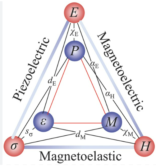
A multi-ferroic material is a type of material that exhibits multiple types of ferroic ordering, such as ferromagnetism, ferroelectricity, and ferro-elasticity, in a single material. In other words, these materials can have more than one ferroic property simultaneously.

Ferroic materials are characterized by the existence of a spontaneous polarization or magnetization, which can be switched or reversed by an applied electric or magnetic field, respectively. Ferromagnetic materials, for example, exhibit a spontaneous magnetization, while ferroelectric materials exhibit a spontaneous electric polarization. Ferroelastic materials exhibit a spontaneous deformation or strain.

Multi-ferroic materials are of great interest because they offer the potential for new types of functional materials and devices, such as magnetoelectric sensors, actuators, and memory devices. For example, a magnetoelectric memory device could store data as both magnetic and electric signals, which could provide enhanced performance and energy efficiency compared to traditional memory technologies. How they are connected each other is shown in figure 1.

Some examples of multi-ferroic materials include bismuth ferrite (BiFeO3), which exhibits both ferroelectric and antiferromagnetic orderings, and lead magnesium niobate-lead titanate (PMN-PT), which exhibits both ferroelectric and ferroelastic orderings. Research is ongoing to explore new types of multi-ferroic materials and to understand the underlying physics that govern their behavior.

Ferroic in one materials?


materials can have both ferromagnetic and ferroelectric characteristics, and such materials are called "magnetoelectric multiferroics." These materials exhibit both magnetic and electric polarizations that are coupled to each other, allowing for control of one property with the other. The coupling between magnetic and electric polarizations in these materials can be exploited for various applications, including magnetoelectric sensors, actuators, and memory devices.

One example of a magnetoelectric multiferroic material is bismuth ferrite (BiFeO3), which exhibits both ferroelectric and antiferromagnetic orderings. Another example is TbMnO3, which exhibits ferromagnetism and ferroelectricity at low temperatures.

Magnetoelectric multiferroics are still an area of active research, and many challenges remain in developing practical devices based on these materials. One challenge is to optimize the coupling between the magnetic and electric polarizations, as this coupling can be weak in some materials. Another challenge is to develop methods for integrating these materials into practical devices with high performance and reliability. However, the potential applications of magnetoelectric multiferroics make them an exciting area of research with significant potential for technological innovation.

Device target and concepts:


Multi-ferroic materials are materials that exhibit both ferromagnetic and ferroelectric properties simultaneously. In other words, these materials possess magnetic and electric ordering that can be controlled by each other. The device concept of multi-ferroic materials involves the development of devices that exploit the unique properties of these materials for various applications.

One such application is in data storage devices, where multi-ferroic materials can be used to develop non-volatile memories. The electric field can be used to control the magnetic state of the material, leading to the possibility of developing magnetic random access memory (MRAM) devices with low power consumption and high speed and vice versa. Figure 2 shows a conceptual device with multiferroic concept. 

Another potential application is in sensors and actuators. Multi-ferroic materials can be used to develop sensors that can detect both magnetic and electric fields simultaneously, which can have applications in medical imaging and non-destructive testing. Additionally, multi-ferroic materials can also be used to develop actuators that can be controlled using either magnetic or electric fields, which can be useful in the development of microelectromechanical systems (MEMS).

Overall, the device concept of multi-ferroic materials has significant potential for various applications, including data storage, sensing, and actuation, and ongoing research in this area is expected to lead to the development of new and innovative devices.

Major challenges:


There are several major challenges associated with magnetoelectric multiferroic materials that are currently being addressed by researchers in the field. Some of these challenges include:

Finding new materials: Currently, there are only a limited number of materials that exhibit both ferromagnetic and ferroelectric properties, and most of these materials have low magnetoelectric coupling. Thus, one major challenge is to find new materials that exhibit strong magnetoelectric coupling and are suitable for practical applications.

Understanding the underlying physics: The physics of magnetoelectric coupling is still not well understood, and more research is needed to understand the mechanisms that govern the coupling between magnetic and electric properties.

Developing practical devices: Magnetoelectric multiferroic materials have the potential to enable new types of devices, such as magnetoelectric sensors, actuators, and memory devices. However, there are still significant challenges associated with developing practical devices based on these materials, such as achieving high sensitivity, reliability, and manufacturability.

Controlling domain structure: The domain structure of magnetoelectric multiferroic materials can have a significant impact on their properties and performance. However, controlling the domain structure of these materials is a significant challenge, and more research is needed to develop effective methods for controlling domain structure at the nanoscale.

Temperature effect: Temperature can have a significant effect on the properties of magnetoelectric multiferroic materials. The ferromagnetic and ferroelectric properties of these materials are often strongly coupled, and changes

Overall, magnetoelectric multiferroic materials are a promising area of research, but there are still many challenges that must be addressed before they can be effectively integrated into practical devices. Please find other fruitful discussion here.


What is ferromagnetism and phase transition? How to extract second order ferromagnetic phase transition from M-T measurement?

Magnetization

    Ferromagnet shows spontaneous magnetization (M) with or without a magnetic field. The magnetization remains without the field. Usually, the alignment of the magnetic moments of electrons gives spontaneous magnetization. The exchange interaction in quantum mechanics explains the interaction of spin-spin controlled by the Coulomb interaction.  The interaction keeps the Pauli principle stable. If the net magnetization is zero in a system that means exchange interaction is zero. If it is high that means all spins are parallel to each other resulting in non-zero magnetization. However, simply if the temperature (T) is increased then thermal energy will randomize the spins and if the T is very high the randomization will be too much resulting in vanishing magnetization. The vanishing of magnetization means the magnetic system is paramagnetic in nature. The temperature at which the magnetic moment of electron spin orientation vanishes is called critical temperature (Tc) or Curie temperature.


Magnetic phase transition

    We know that the phase transition is usually governed by pressure, chemical composition, temperature, electric or magnetic field, and connected with order. We see two types of phase transition: one is first order and the other is one-second order. The first-order phase transition is discontinuous with entropy and hence with latent heat. For example, if we heat an ice bar at a constant rate, the temperature remains the same until we reach zero degrees Celsius. The heat we put to become zero degrees is the latent heat of transformation. The first order is also known as sudden volume change. For example, ice enlarges relative to water when they transfer to each other i.e. sudden change in volume. On the other hand, a second-order phase transition does not carry any latent heat with it. The entropy is continuous at a critical temperature. Figure 1 (a) and (b) show the graphical representation of the ferromagnetic and paramagnetic nature of the magnetic moment of electron spin. 


Figure 1: (a) ferromagnetic (b) paramagnetic electron spin moment.


Figure 2 shows the first-order and second-order phase transition behaviors concerning temperature.


a) first-order (b) second-order magnetic phase transition
Figure 2. (a) first-order (b) second-order magnetic phase transition 


Magnetic second-order phase transition evaluation

For technical people, it is necessary to extract magnetization transition temperature for application-related or further consideration-related issues. The detailed process is usually in journal papers or proceedings that do not highlight it. Because that is a technical point usually people keep with them. Therefore, understanding how to evaluate magnetic transition, specifically second-order phase transitions is important and necessary to evaluate properly. We consider magnetic thin film having ferromagnetism which is technologically important for spintronic devices like GMR, TMR, spin FET, or novel applications. First, we can measure (SQUID, VSM methods) the saturation magnetization field from the M-H graph (figure 3). Also, from the M-H result, we can easily extract coercive fields to design magnetic devices.

Saturation magnetization determination
Figure 3: Saturation magnetization determination 

Second, use the saturation magnetization field as an applied magnetic field and measure temperature-dependent magnetization, and normalize the magnetization by the volume of the magnetic thin film. Sometimes we need to subtract the background part if there are other film or substrate contributions like diamagnetic involved in the sample. Finally, the first derivation of the M-T curve gives a transition temperature at the minimum of the first derivation. The measurement of M-T and extracted graph are shown in figure 4 (a), and (b) respectively. By this technique, one can successfully extract the important Curie temperature of the magnetic thin film. 

(a) M-T curve and (b) first derivative of M-T minima is the second-order transition point
Figure 4: (a) M-T curve and (b) first derivative of M-T minima is the second-order transition point 

You can also learn about Schottky diode-related related problems.